A few weekends ago I decided to create a test node for the The Things Network (TTN) gateway in Sydney and purchased a RFM95W 915MHz LoRa Transceiver module hoping to hook it up to an Arduino using a port of the LMiC (LoraWAN-in-C, formerly LoraMAC-in-C) framework provided by IBM. In my haste I didn’t realise most libraries didn’t support the Australian frequency.
Tip – If you don’t want to use LMiC you should look at a LoRaWAN module. These basically integrate a LoRa transceiver with a microcontroller for the LoRaWAN protocol. I believe the most common module (pre-programmed with the Australian frequencies) is the Multitech mDot LoRaWAN module (http://www.multitech.com/models/94557148LF )
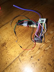
After a few trials and tribulations I managed to cobble together a very rough node with sensor from the limited parts I had on hand.
Parts
- RFM95W 915MHz LoRa Transceiver
- Arduino Pro Mini – ATmega328, 3.3V and 8MHz (Note. I used a compatible board easily sourced in Australia http://modtronix.com/ard-promini328p3.html ) Tip – If you use a 5V Arduino you will need to use a level shifter to get it to approximately 3.3V.
- Photocell
- 10KΩ resistor Tip – Depending on where you plan to use the sensor you may want to use a lower resistor. Unfortunately all I had on hand was a 10K though I would have been better served by a 1KΩ Read more here: https://learn.adafruit.com/photocells/using-a-photocell
- Wires
- Pin headers (Not required but useful for a test node)
- I had a battery pack 4 x AA (6V), hence had to connect to RAW input (Max 12V on RAW input).
- Arduino Pro Mini USB Programmer (Reminder – Select 3.3V if using a Arduino Pro Mini 3.3V)
Wiring
As I wanted to use this as a test node I basically did a three step process.
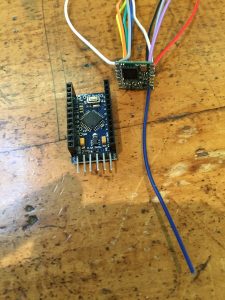
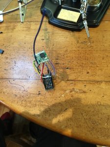
- Solder wires to RFM95W (Note. For the antenna I just used a straight wire. Therefore ¼ wave 915-928 you want a wire length around 81-82 mm)
- Solder headers to Arduino Pro Mini
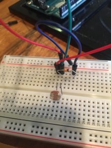
- Solder Sensor together (Photocell + 10KΩ resistor)
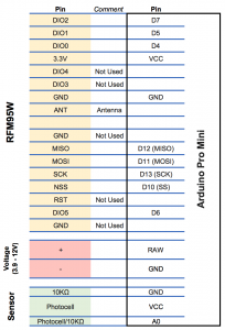
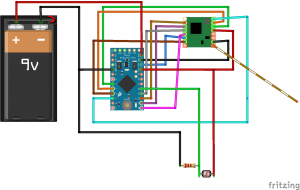
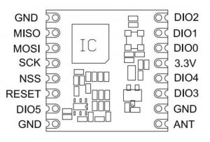
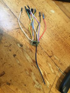
Programming the Arduino
First step was to configure the library (https://github.com/matthijskooijman/arduino-lmic ) for Australian frequencies.
After doing a bit of reading I found the TTN gateways in Australia support between 915 – 928 (https://github.com/TheThingsNetwork/ttn/issues/120
https://www.thethingsnetwork.org/wiki/LoRaWAN/Frequencies/Frequency-Plans and https://www.thethingsnetwork.org/country/australia/) and after cross-checking against the Multitech MDot LoRA library (https://developer.mbed.org/teams/MultiTech/code/libmDot/file/b50f92f1c6ff/Lora.h) I modified the US915 configuration to match the Australian frequency.
Note. Depending on what transceiver you decide to use remember to change your config.h for the correct configuration (for the RFM95W use ‘ #define CFG_sx1276_radio 1’)
All code I used for the test node (both OTAA and ABP) can be found here – https://github.com/Mailbox11-Rep/TTN-Test-Node . I know I should have forked but I didn’t! Basically I modified the OTAA and ABP examples to send the Photocell readings.
TTN – Payload functions (decoder)
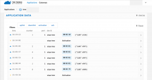
I will assume that you know how to establish a TTN application and get the required device id etc. One thing that you will need to do if you want to see your payload data via TTN console is add a decoder. For the Photocell example I have provided you can use the following.
function Decoder(bytes, port) {
// Decode an uplink message from a buffer
// (array) of bytes to an object of fields.
var decoded = {};
// Decode bytes to int
var pcInt = (bytes[1] << 8) | bytes[2];
// Decode int to float
decoded.LUX = pcInt;
return decoded;
}
Result
I ended up getting a 1.7km straight line of sight range (though poor weather skewed this). With a more solid antenna and a less cobbled together node I am sure this range would be improved considerably.

3 Comments
Hi,
I’m planning on using the AU915 frequencies in New Zealand.
I’m interested to know the exact changes you made to support the AU915 Frequency Plan.
Could you please contact me by email (I don’t use twitter!)?
Thanks
John
I have edited this article to point to The Things Network Frequency pages for AU.
https://www.thethingsnetwork.org/wiki/LoRaWAN/Frequencies/Frequency-Plans
https://www.thethingsnetwork.org/country/australia/
Hi John I just checked and it does seem New Zealand has adopted AU frequencies (https://www.thethingsnetwork.org/forum/t/frequency-plan-new-zealand/6846)
As such the exact changes I made to support the AU915 Frequency plan are under the lorabase.h file (arduino-lmic-master/src/lmic/lorabase.h) [https://github.com/Mailbox11-Rep/TTN-Test-Node/blob/master/libraries/arduino-lmic-master/src/lmic/lorabase.h]
Look for this section of code
// Default frequency plan for US 915MHz
enum { US915_125kHz_UPFBASE = 915200000,
US915_125kHz_UPFSTEP = 200000,
US915_500kHz_UPFBASE = 915900000,
US915_500kHz_UPFSTEP = 1600000,
US915_500kHz_DNFBASE = 923300000,
US915_500kHz_DNFSTEP = 600000
};
enum { US915_FREQ_MIN = 915000000,
US915_FREQ_MAX = 928000000 };
As I was lazy I used the existing construct for US915 and just changed the frequencies under this. As such if you are using my code under the config.h file you need to ensure us915 is enabled (#define CFG_us915 1).
Hope this helps.
Cheers